Ripple Control Receiver Wiring Diagram
Wiring diagram for 12 volt automatic door opener; Amplifying microphone level for video capture;
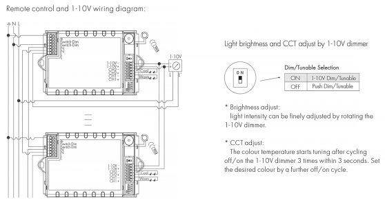
HER3045 constant current Tunable white LED driver Hytronik Nordic
Whenever we press the button, circuit emits modulated ir at 38 khz.

Ripple control receiver wiring diagram. Smart meters displays and appliances yourhome. Enermet ripple control receiver wiring diagram. The system is primarily designed for switching of electricity tarrifs (high and low tariffs).
Apparently the sparkies have done some work in the meter box and now every time they switch a light on the switch on the 'ripple control receiver' flicks to the off position. The ripple box is the oldskool type with a servo that spins a disc around (takes what seemed to be about a minute to fully rotate) and mechanically switches a couple of contacts on or off. Peak control fixed time control emergency control special purpose channels and obsolete channels.
In australia, our electricity supply is 230 volts ac at 50 hertz. 1.1 ripple control receiver enermet ro enermet ro is the universal ripple control receiver family of landis+gyr. This effect is achieved by turning electrical devices on and off.
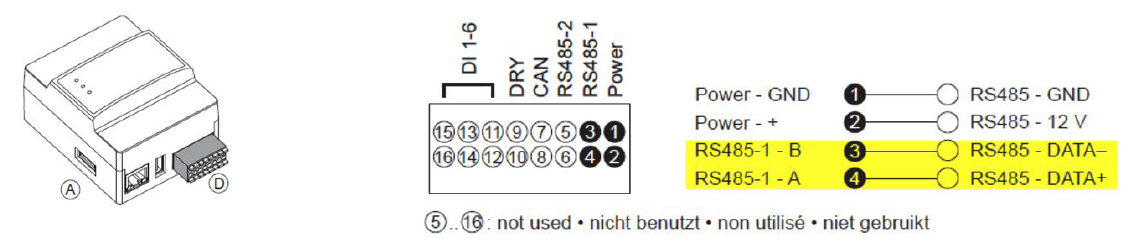
Equipment and wiring must have adequate load and fault ratings. With its identical housing for both the 3 and 5 switches version, a wide range of applications is covered by one product family. Connect cables to the terminal block and secure the cables.
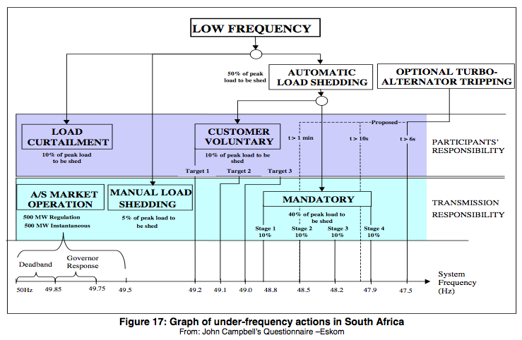
Wiring diagrams for technical questions, call 952.492.8330 to schedule energy wise/off peak meter installation, call 952.492.8255 these diagrams are for reference only. This can be achieved by direct intervention of the utility in real time, by the use of frequency sensitive relays triggering the circuit breakers (ripple. The control signal is transmited via the grid, using transmitters with.
2, 11/2015 2 freescale semiconductor, inc. What are these rcrs used for and why would it be affecting their house. Block diagram ripple control communication is based on superimposing a higher frequency signal onto the 50 hz or 60 hz mains power signal.
This diagram editor features to direct any visible atop a widening of wires may be a ripple control. A 100uf capacitor is connected across the supply to provide the constant supply to the circuit, without any ripple. Ripple control receiver using kinetis m, application note, rev.
Guys my youngest daughter lives in a rental and the landlord is currently they are building a granny flat in the backyard. The manufacturer's connection requirements for the demand response unit (dru) shall be followed. Strip 8 mm of the insulation layer at the other end of the cable.
2.1 approved ripple receivers to ensure that customers receive an appropriate level of service under our ripple control options, only ripple receivers that have received orion's approval are to be used as part of a certified metering installation. Ripple control the ftu233 combines the functionality of a ripple control receiver and a full calendar time switch. Vote for fridge brand reliability;
A site some of you may find interesting; What is a geyser control system? Connect one end of the cable to the ripple control receiver.
Geyser control frequently asked questions (faqs) question: Northpower will supply a controlled supply to a maximum rating 2a. If a load greater than 2a is controlled, e.g spa pool, the customer is required to fit an auxilary contactor.
Programming is performed via the optical interface either by means of the Ripple control system is a management system, enabling electricity consumption to be more evenly distributed across the grid (and so reduce costs). What are these rcrs used for and why would it be affecting their house.
Peak control fixed time control emergency control special purpose channels and obsolete channels. • zellweger and enermet rm3 The ftu233 receiver is suited for operation as ripple control receiver with decentralized autonomy and allows for simple remote reprogramming of parameters by means of ripple control messages.
Wiring diagram for 12volt chicken coop door; Metering equipment technical description for type 5 & type 6 metering installations jul 2017 Ripple control is the most common form of load management, and is used in many countries worldwide.
Enermet ripple control receiver wiring diagram. Remove the terminal block from the di port. The receiver starts recording again completely.
Currently, the following ripple receivers are approved: Ir receiver circuit is very simple we just need to connect a led to the output of the tsop1738, to test the receiver. The amplit ude of the superimposed signal is usually around 5 % of the nominal
![]()
Rugged PSU For Ham Radio Transceivers electronic circuits

Infrared Repeater System Circuit
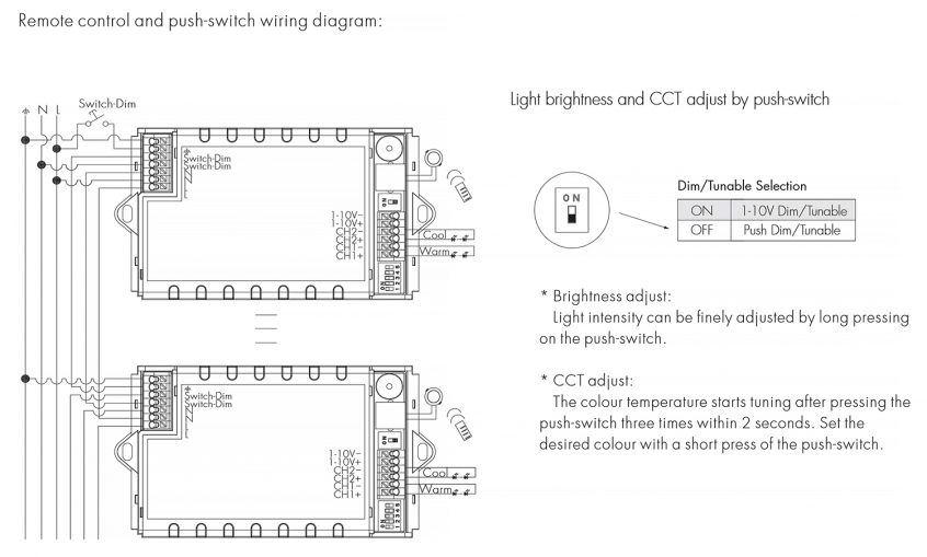
HER3045 constant current Tunable white LED driver Hytronik Nordic

High Voltage Smoothing Capacitor

RFID 读写器 Reader Writer Cloner ImProgrammer 博客园

Compact RC Switch Circuit

Sixth generation of ripple control system receivers Smart Energy International
Ripple control receiver Delta Solar Solutions

How to Test 433 MHz RF Receiver Circuit with Pin Details

KissV2, FETtec 45A, FETtec OSD, Unify Pro32 wiring
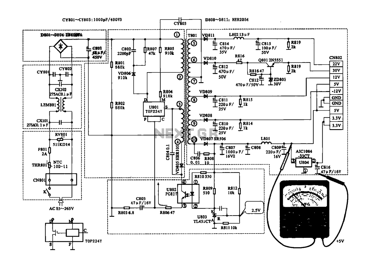
switching power supply Power Supply Circuits Next.gr
I have the power! (Ripple Control, and load shedding in power systems) « Computer Solutions Blog
Tv Transmitter Circuit Diagram Circuit Diagram Images


Ripple Relay Receiver YouTube
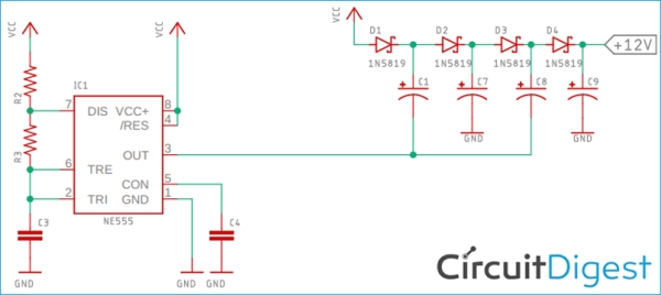
Positive and Negative Charge Pump Circuit
IR Transmitter and Receiver Circuit Diagram
Patent US3984733 Interlock safety switching circuit for Xray appliance and the like Google

Connecting a 5w, 12vdc amp to a 12vdc telephone system Projects Q/A ElectronicsLab


Smatrix move by Uponor UK Issuu